

High Speed Homogenizer: Types Diagrams and 2-Stage Design
When Elena, a process engineer in Valencia, increased the speed of a pilot homogenizer to rescue a separating emulsion, the outlet became warmer, the pressure signal fluctuated, and the particle-size result varied between samples. This illustrative scenario shows why a faster motor is not automatically a better process. The root cause can be a mismatch between the mechanism, feed condition, valve setting, pass count, and sampling plan. A defensible design starts by defining the quality endpoint, then matching flow, energy exposure, cooling, and documentation to that endpoint. This guide gives process engineers and procurement teams a practical way to compare types, read a diagram, evaluate a two-stage configuration, and plan scale-up without treating a nameplate claim as process evidence.
Summary: A high speed homogenizer creates a more uniform emulsion or dispersion by forcing a compatible feed through a controlled high-shear or high-pressure interaction zone; speed alone does not determine the result. In a two-stage high-pressure design, the first stage normally supplies the main pressure drop and the second stage provides controlled secondary treatment and back-pressure management, with the exact duty depending on valve geometry and formulation. Use a homogenizer machine diagram to verify the feed path, stages, cooling, instrumentation, and safe discharge. Define the target size or stability test, record pressure, flow, temperature, and passes, and ask for representative trial data before approving capacity.
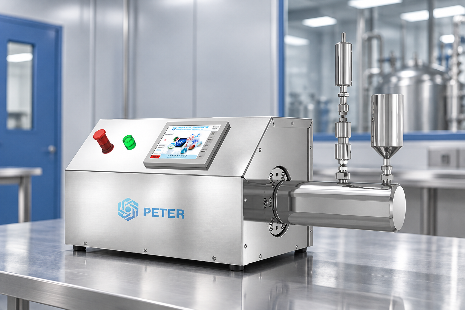
What does a high-speed homogenizer change in a process?
Homogenization is a controlled way to reduce differences in droplet or particle size, improve dispersion, or disrupt cells. In a pressure-driven system, a pump sends a liquid through a narrow interaction zone; pressure drop, turbulence, shear, and cavitation can break dispersed structures. In rotor-stator equipment, a rotating element creates local shear in a small gap. An ultrasonic unit couples acoustic energy into the feed. These mechanisms are related in purpose but differ in throughput, heat generation, cleanability, and scale-up behavior.
The phrase high speed homogenizer can describe a rotor-stator mixer, an inline high-shear unit, or a marketing name for a pressure system. The request for quotation should therefore state the physical mechanism, the acceptable feed envelope, and the measured endpoint. For particle-size work, ISO 13320 describes laser-diffraction analysis and ISO 22412 describes dynamic-light-scattering analysis for suitable dispersed systems. Both are measurement methods; neither certifies a machine or guarantees storage stability.
How should engineers read a homogenizer machine diagram?
A homogenizer machine diagram is useful when it shows the sequence that the product actually follows. Start at the feed vessel and trace the inlet pump, filter or deaeration point, pressure gauge, first interaction valve, second-stage valve or back-pressure element, cooler, discharge, and sampling point. The diagram should also identify product-contact materials, drain points, isolation valves, relief protection, and instrument locations. If a drawing omits a component that affects pressure, temperature, or cleaning, ask for a revised process and instrumentation diagram before comparing quotations.
Diagram review should answer four practical questions. Is the inlet stable enough to prevent cavitation? Can the cooler remove the heat added at the selected duty? Can operators isolate and depressurize every pressure boundary? Can the line be drained and cleaned without leaving a trapped product pocket? A clear flow path also makes commissioning easier because technicians can connect each alarm, sample, and valve position to a defined process step.
What are the types of homogenizer used in B2B processing?
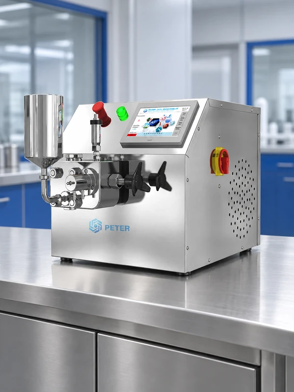
The phrase types of homogenizer should be read as a mechanism and duty classification, not a ranking. High-pressure valve systems suit pumpable liquids that need repeatable droplet or particle reduction. Rotor-stator systems are often used for premixing, wet-out, deagglomeration, and batch or inline high-shear work. Ultrasonic processors can be useful for smaller laboratory volumes where acoustic energy and cooling are controllable. Bead or media mills add grinding media and are selected when the process requires that distinct energy path. Product names overlap, so mechanism and acceptance test matter more than the label.
| Mechanism | Typical strength | Critical limits to verify | Hidden TCO drivers |
|---|---|---|---|
| High-pressure valve | Continuous emulsion or dispersion finishing for pumpable feeds | Inlet stability, pressure, viscosity, solids, temperature rise, pass count | Valve and seal wear, cooling duty, pressure-boundary inspection, spare parts |
| Rotor-stator | Fast premixing, wet-out, and deagglomeration in a tank or inline loop | Tip speed, gap, air entrainment, shear heating, head wear, scale-up similarity | Drive and bearing service, seals, tank cleaning, recirculation time |
| Ultrasonic | Localized laboratory dispersion or cell-disruption studies | Amplitude, duty cycle, probe condition, foaming, heat removal, batch volume | Probe replacement, cooling, acoustic controls, sample loss at small scale |
| Bead or media mill | Fine grinding or dispersion when media contact is acceptable | Media separation, screen loading, contamination, viscosity, recirculation | Media consumption, product hold-up, cleaning, screen and seal replacement |
How does a 2-stage homogenizer work?
The practical answer to how does a 2 stage homogenizer work is that the feed passes through two controlled treatment zones in sequence. The first stage generally delivers the primary pressure drop and most of the droplet or agglomerate break-up. The second stage then applies a defined secondary pressure drop or back-pressure condition; it can reduce re-agglomeration, tune the final distribution, and make the process less sensitive to an abrupt discharge condition. The useful split is design-specific, so a supplier should show pressure, flow, temperature, and endpoint data for the actual formulation.
A two-stage setup is not automatically superior. The additional valve, seals, pressure instrumentation, and cooling demand add maintenance and validation work. A single-stage unit may be sufficient when the formulation reaches its endpoint in one interaction zone and the downstream line can manage the discharge. Conversely, a second stage may be justified when a first-stage result is broad, when the product re-agglomerates, or when the process needs a controlled back-pressure condition. Compare both configurations at the same accepted throughput and analytical method.
| Decision dimension | Single stage | Two stage | Evidence to request |
|---|---|---|---|
| Energy path | One principal interaction zone | Primary treatment followed by controlled secondary treatment | Pressure and flow at each stage; product temperature after the pass |
| Product result | May be adequate when one pass reaches the endpoint | May narrow or stabilize the result when the feed benefits from staged treatment | Particle-size distribution, stability or release test after each stage |
| Maintenance | Fewer wear items and a simpler flow path | Additional valve, seals, instruments, isolation, and cleaning checks | Wear-part list, inspection interval, drainability, and spare strategy |
| Scale-up risk | Scale the validated pressure, flow, and pass count | Preserve the relationship between stage pressures, flow, residence time, and cooling | Pilot-to-production transfer protocol and repeat-batch data |
For a detailed valve discussion, see CAS PETER’s high-pressure homogenizer valve-design guide. The how does a 2 stage homogenizer work question should be answered with the selected valve arrangement and measured product outcome, not with a generic claim that two stages always halve particle size.
Which settings control performance, heat, and repeatability?
Critical settings interact. Pressure or rotor speed controls the available energy, but flow, viscosity, solids loading, inlet pressure, temperature, gas content, pass count, and residence time determine how the product experiences that energy. A homogenizer machine diagram helps teams place gauges and sensors where those variables can be seen. Trend pressure fluctuation and flow together; a gradual change can indicate valve or seal wear before the product visibly fails.
Set operating windows rather than one nominal setpoint. Record the minimum stable inlet condition, target pressure or speed, maximum product temperature, allowed pressure fluctuation, acceptable feed solids, and action limits for alarms. If the feed is shear-sensitive, specify cooling capacity and a hold-time limit. If the feed is abrasive, specify the material and replacement plan for the interaction zone. During trials, retain raw readings and sample identifiers so the final specification can be audited.
- Pressure or speed: increase only while the accepted endpoint improves; excess energy can add heat, wear, and cost without a useful product change.
- Flow and pass count: a nominal flow rate is not an accepted throughput until the product meets its test after the stated number of passes.
- Temperature: measure inlet and outlet temperature; add cooling or a lower exposure time when formulation stability requires it.
- Sampling: define location, timing, container, mixing state, dilution, and analytical method; appearance alone is not a release test.
- Feed preparation: control premixing, filtration, deaeration, and particle-size range upstream so the homogenizer is not asked to solve unrelated problems.
How should applications and scale-up be planned?
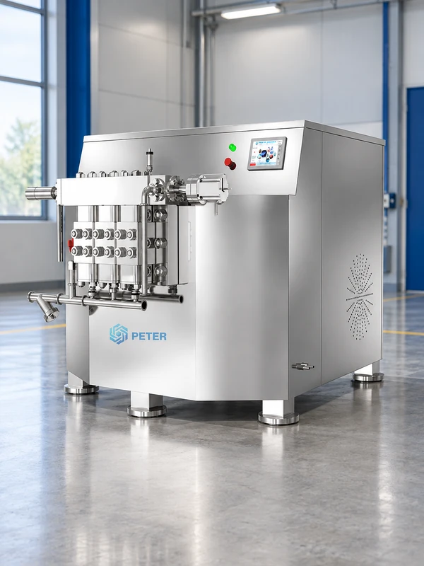
Application fit depends on the product’s dominant constraint. Food and beverage teams may prioritize emulsion stability, cleanability, and a repeatable hourly rate. Pharmaceutical and biotech teams may add controlled sampling, traceable materials, and a documented validation strategy. Cosmetics and specialty chemicals may need a defined viscosity range, temperature limit, or solids handling plan. Laboratory development teams usually value low hold-up volume and quick changeover, while pilot teams need a credible bridge to production.
| Use stage | Primary question | Data to carry forward | Documentation |
|---|---|---|---|
| Laboratory | Can the mechanism create the target endpoint without overheating or losing sample? | Feed composition, pressure or speed, pass count, temperature, sample preparation | Trial protocol, raw readings, analytical method, cleaning notes |
| Pilot | Does the result remain stable as flow and batch size increase? | Stable operating window, stage relationship, cooling load, residence time, repeatability | Flow path, utility schedule, acceptance test, wear-part plan |
| Production | Can accepted throughput meet demand within cleaning and maintenance windows? | Peak and normal demand, cycle time, changeover, redundancy, service access | Commissioning package, manuals, drawings, training, spare strategy |
An illustrative throughput calculation is accepted throughput = usable batch volume divided by total cycle time. If a 120 L batch needs 45 minutes of homogenization plus 25 minutes for charging and discharge, the average before cleaning is about 103 L/h; the figure is only a planning illustration until plant measurements replace the assumptions. Include cooling, sampling, cleaning, and planned maintenance in the real cycle. Scale pressure and flow around the measured endpoint, not by copying motor speed or vessel volume alone.
What should procurement request from a supplier?
CAS PETER’s homogenizer range can be used as a starting point for mapping experimental, pilot, and production duties. The PT-20 high-pressure homogenizer and pilot-type PT-40 pages should be reviewed against the written feed, endpoint, and capacity requirement. Buyers should confirm current configuration details, test scope, materials, utilities, and documentation with the supplier before issuing a purchase order.
- Write the endpoint: state the particle-size, stability, assay, or release criterion and the method used to measure it.
- Describe the worst feed: provide viscosity at operating temperature, solids, density, air sensitivity, temperature limit, and particle-size range.
- Request a two-stage trial: compare single-stage and two-stage settings at the same feed, throughput, and sampling plan.
- Request complete drawings: obtain the flow path, stage pressures, relief and isolation points, cooling, drains, sensors, and product-contact materials.
- Price lifecycle work: include installation, training, cleaning, validation support, wear parts, spare response, service access, and expected downtime.
What standards and compliance checks apply?
Requirements depend on the destination market, sector, materials, and claims. ISO 12100 provides principles for machinery risk assessment and risk reduction; it is not a product certificate. ISO 13320 and ISO 22412 support different particle-size measurement approaches. For U.S. food operations, 21 CFR 117.35 addresses sanitary operations; for drug manufacturing, 21 CFR 211.110 addresses in-process sampling and testing. EHEDG guidance can inform hygienic design and cleanability reviews where relevant. Ask for the exact declaration, test record, material information, and operating limits applicable to the selected configuration.
Unsupported statements such as “sterile,” “FDA approved,” or a guaranteed micron size can create commercial and validation risk. A standard test method does not certify the machine, and a supplier’s demonstration with water does not prove performance with a viscous or abrasive formulation. Keep the compliance statement aligned with the equipment configuration, the intended use, and the quality system that will release the product.
Frequently asked questions
What is the working principle of a homogenizer machine?
A homogenizer machine applies controlled mechanical or acoustic energy to a feed so droplets, particles, or cells experience a repeatable breakup or dispersion step. High-pressure systems use a pump and interaction valve; rotor-stator systems use a narrow rotating gap; ultrasonic systems use acoustic cavitation. The final result depends on feed condition, energy input, temperature, pass count, and the analytical method used to verify it.
How does a homogenizer machine create a uniform product?
It reduces the size differences or concentration gradients that cause visible separation, settling, or inconsistent sampling. A high-pressure unit creates a controlled pressure drop, while other mechanisms apply local shear, acoustic energy, or media contact. Uniformity must be demonstrated with a defined particle-size, stability, assay, or visual-uniformity test at a representative sampling point.
What is the role of homogenizer machine diagram in the process?
A homogenizer machine diagram shows how feed, stages, pressure controls, cooling, sampling, and discharge are connected. Engineers use it to check inlet stability, relief and isolation points, cleanability, instrument locations, and the relationship between first-stage and second-stage treatment. Request an updated process and instrumentation drawing when a quotation leaves out a component that affects safety, temperature, pressure, or cleaning.
Which process settings affect homogenizer machine performance?
Pressure or speed, flow, viscosity, solids loading, inlet pressure, temperature, air content, pass count, residence time, and sampling method all affect the result. Valve, seal, rotor-stator, or probe wear can change performance over time. Record these settings with the product test and define operating limits before scaling the process.
Conclusion: specify the endpoint, then the stages
The useful meaning of types of homogenizer is the mechanism’s fit to a measured process duty. A two-stage unit can provide a controlled primary and secondary treatment, but it also adds pressure-boundary, cooling, cleaning, and maintenance decisions. Define the endpoint, characterize the feed, compare one- and two-stage trials, and carry the validated variables into the scale-up file. For a structured application review, start with CAS PETER’s homogenizer product directory and contact the technical team with the formulation, capacity, test method, and compliance context.
References
- ISO 13320: Particle size analysis – Laser diffraction methods. International Organization for Standardization.
- ISO 22412: Particle size analysis – Dynamic light scattering. International Organization for Standardization.
- ISO 12100: Safety of machinery – General principles for design. International Organization for Standardization.
- 21 CFR 117.35, Sanitary operations. U.S. Electronic Code of Federal Regulations.
- 21 CFR 211.110, Sampling and testing of in-process materials and drug products. U.S. Electronic Code of Federal Regulations.