

How Does a High Pressure Homogenizer Work? Valve Design
A common valve-design misunderstanding is that the pressure gauge alone describes what the product experiences. It does not. Two runs at the same indicated pressure can produce different particle or droplet distributions when the valve or interaction chamber differs, the feed contains air, flow changes, the inlet temperature shifts, or “one pass” is defined differently. Treating pressure as the complete recipe can waste material, accelerate wear, and create a scale-up record that another team cannot reproduce. The useful boundary is therefore not a universal claim about cavitation, shear, or impact. It is a documented pump-to-valve sequence tied to a specific feed, interaction approach, flow, thermal history, pass definition, sampling plan, and analytical method. This article shows how to build that defensible process description.
The short answer to “how does a high pressure homogenizer work?” is that a pump delivers a pumpable feed at controlled pressure to a restricted valve or interaction zone; the rapid pressure drop and resulting flow field apply intense, localized stresses before the product exits and is cooled or collected. The contribution of shear, extension, turbulence, impact, and cavitation depends on geometry and fluid conditions, so no single mechanism explains every machine or formulation. Record actual pressure, flow, inlet and outlet temperature, and pass history. Then verify the result with a suitable method—for example, ISO 13320 laser diffraction or ISO 22412 dynamic light scattering—rather than treating either standard as equipment certification.
How the pump and valve create the homogenizing effect
The process begins before the high-pressure pump. The feed must be sufficiently pumpable, mixed, and free of oversized material that exceeds the supplier’s inlet limits. Its viscosity, solids or oil fraction, pH, initial size distribution, temperature, and tendency to foam all affect delivery. A coarse premix may be necessary for an emulsion, but a rotor-stator premix and a high-pressure finishing step perform different jobs. The pump must receive a stable liquid supply; starvation, entrained air, or volatile flashing can disrupt pressure generation before the product reaches the homogenizing zone.
A positive-displacement pump commonly raises the liquid pressure, although the exact pumping architecture is equipment-specific. The pressurized feed then approaches a controlled restriction or interaction path. Across that zone, static pressure falls rapidly while local velocity and deformation rates rise. Depending on the design, the fluid may experience combinations of elongational and shear stress, turbulence, rapid deceleration, impingement, and cavitation. A peer-reviewed study of a particular jet-valve system varied pressure, emulsion temperature, and cycle count and observed that all three belonged in its control strategy; that is evidence for a multivariable recipe, not proof that every valve behaves identically [1].
The interaction zone is therefore a process boundary, not a promise of one universal breakup mechanism. In high-pressure homogenization, droplets may deform and break, agglomerates may disperse, or cells may be disrupted when local stresses exceed the relevant structural resistance. Newly created interfaces also need adequate stabilizer coverage; otherwise, smaller droplets can collide and recoalesce. A uniform-looking sample at the outlet is not sufficient evidence of long-term stability, and a pressure setting alone cannot predict biological yield, particle-size distribution, or shelf life.
How valve design changes the pressure drop
“Valve design” should be specified at the level needed to reproduce the process without inventing proprietary geometry. Useful descriptors include single-stage or two-stage operation, adjustable-valve or fixed-path interaction approach, pressure allocation by stage, flow direction, cooling arrangement, and the manufacturer’s named valve or chamber class. Internal dimensions, impact surfaces, or channel networks should be recorded only when the supplier provides them. A similar maximum pressure does not establish equivalent local stresses, residence-time distribution, heat generation, wear behavior, or feed tolerance.
In a single-stage system, the primary pressure drop occurs across one controlled stage. In a two-stage system, the first stage commonly carries the main treatment load while the second applies a smaller, separately controlled pressure drop that may help manage clusters or downstream flow behavior. That description is deliberately conditional: the pressure split and intended function must come from the equipment documentation and the product study. “Two stage” does not mean two equal treatments, and two pressure gauges do not automatically represent two full passes.
| Generic interaction approach | How pressure drop is arranged | What the process team should verify | What cannot be inferred from the label |
|---|---|---|---|
| Single-stage adjustable valve | One primary controlled stage | Working pressure, verified flow, feed limits, temperature rise, valve setting, and wear baseline | A single dominant breakup mechanism or universal particle size |
| Two-stage valve | A primary stage followed by a separately controlled second drop | Pressure at each stage, the supplier-defined purpose of stage two, flow, and sampling location | Equal energy at both stages or two complete passes |
| Fixed-path interaction chamber | Pressure is released through a manufacturer-defined flow path | Chamber class, compatible feed range, working pressure and flow, cooling, hold-up, and cleaning access | Undisclosed channel geometry, equivalence to another chamber, or product-specific performance |
The comparison is about verification, not ranking. Procurement teams should request a process schematic, pressure definitions, continuous working limits, acceptable feed conditions, product-contact materials, wear-part list, and cleaning route for the proposed configuration. A model comparison is meaningful only when the formulation, target attributes, working pressure, measured flow, temperature window, and pass protocol are comparable.
Record feed conditions and run history for repeatable results
Feed condition is the first practical control. Record the formulation identifier and lot, premix method, concentration, pH, viscosity with measurement temperature, incoming particle or droplet distribution, maximum visible or screened particle condition, and inlet temperature. Confirm chemical compatibility and avoid assuming that a water-based nominal flow applies to a viscous, concentrated, fibrous, abrasive, volatile, or oxygen-sensitive feed. If air is entrained, allow appropriate de-aeration or revise the feed method within product constraints.
Inlet cavitation and air entrainment are not interchangeable with useful cavitation that may occur in or downstream of a valve. On the suction side, insufficient inlet head, restrictions, foaming, high temperature, or volatile components can reduce pump filling and cause pressure pulsation, abnormal noise, or inconsistent flow. Entrained gas is compressible and can make the pump-to-valve delivery uneven. The safe response is to check the feed vessel, suction path, temperature, viscosity, seals, and manufacturer limits—not to close the valve further and call the higher gauge reading a fix.
For every run, record set and observed pressure, pressure by stage where applicable, measured or otherwise clearly identified flow, inlet and outlet temperature, cooling conditions, elapsed time, valve or chamber identifier, and deviations. Pressure energy ultimately appears largely as heat and dissipative losses, but the actual temperature rise depends on the fluid, design, heat transfer, and measurement point. Temperature is therefore both a product-risk variable and a clue about changing flow or restriction.
Define “pass” before comparing trials. In a discrete-pass batch, one pass means the defined usable batch traverses the interaction zone once, with receivers and line hold-up managed so treated and untreated material are not unintentionally mixed. In recirculation, cumulative processed volume divided by usable batch volume can be reported as batch-volume equivalents, but one equivalent does not prove that every fluid element received exactly one treatment. The related benchtop pilot-scale guide explains why pass accounting, hold-up, and sampling must travel with the pressure record.
Check the inlet and product before increasing pressure
Wear and fouling often appear as trends rather than sudden failures. At a fixed recipe, watch pressure stability, measured flow, valve position or adjustment, outlet temperature, noise, vibration, leakage, product recovery, and the agreed quality attribute. Establish a clean, known-good baseline after installation and after qualified maintenance. A drifting particle-size result may reflect valve wear, but it may also reflect feed variation, analytical preparation, temperature, sampling time, or stabilizer performance.
| Observed symptom | Verify before assigning a cause | Evidence-based action |
|---|---|---|
| Pressure or flow fluctuates | Feed level, suction restriction, air, viscosity, pump filling, seals, and pressure-sensor status | Stabilize the inlet and inspect the pump before changing the valve setting |
| Abnormal inlet noise or vibration | Available inlet head, feed temperature, volatility, foam, blocked screens, and loose components | Stop within the operating procedure; remove the verified inlet cause or contact the supplier |
| Quality result drifts at the same recipe | Feed lot, premix, actual flow, temperature, pass history, sampling point, analytical preparation, and valve condition | Repeat against a retained baseline and inspect wear only after measurement and feed causes are checked |
| Outlet temperature rises unexpectedly | Inlet temperature, cooling duty, flow, restriction, sensor location, and fouling | Restore the validated thermal window; do not accept the batch on pressure alone |
| Leakage or failed cleaning check | Seal condition, assembly, compatible chemistry, cleaning parameters, rinse sample, and method suitability | Quarantine as required, repair, reclean, and repeat the approved verification |
Define what the test method can actually prove
Sampling must separate startup material from steady-state material and identify the collection point, time, temperature, and pass history. Use the same container, hold time, mixing method, and sample preparation for comparisons. For laser diffraction, ISO 13320:2020 defines a particle-size analysis method and relevant controls [2]. For dynamic light scattering, ISO 22412:2017 defines a DLS method [3]. Neither standard certifies a homogenizer, and results from the two techniques should not be treated as interchangeable without a justified correlation.
In pharmaceutical development, ICH Q8(R2) provides a framework for relating material attributes and process parameters to critical quality attributes [4]. That supports a product-specific study of pressure, temperature, passes, and feed condition, not a universal validated setting. A laboratory trial, particle-size method, or equipment purchase therefore does not by itself make a process validated or an item of equipment “FDA certified.”
Cleaning has the same boundary. A rinse that looks clear is not cleaning validation. The team must define product-contact surfaces, disassembly or clean-in-place coverage, cleaning chemistry, time, temperature, flow, drainability, residues of concern, acceptance limits, sampling locations, method recovery, and reassembly checks according to the application and quality system. Research use may require documented cleaning verification; regulated manufacture may require a formally validated procedure. Sterilization, hygienic design, containment, and material compatibility are separate questions and must be supported by the proposed model’s documentation.
Use the process window to compare valve configurations
Before requesting a quotation, define the usable batch volume, feed envelope, target quality attributes, analytical methods, temperature ceiling, required throughput, discrete-pass or recirculation plan, cleaning regime, containment needs, utilities, and scale-up destination. Ask suppliers to state the test fluid and conditions behind pressure and flow claims, distinguish maximum from continuous working limits, and identify expected wear checks. Compare total ownership cost through product loss, cooling, cleaning time, wear parts, analytical effort, operator time, and downtime rather than headline pressure alone.
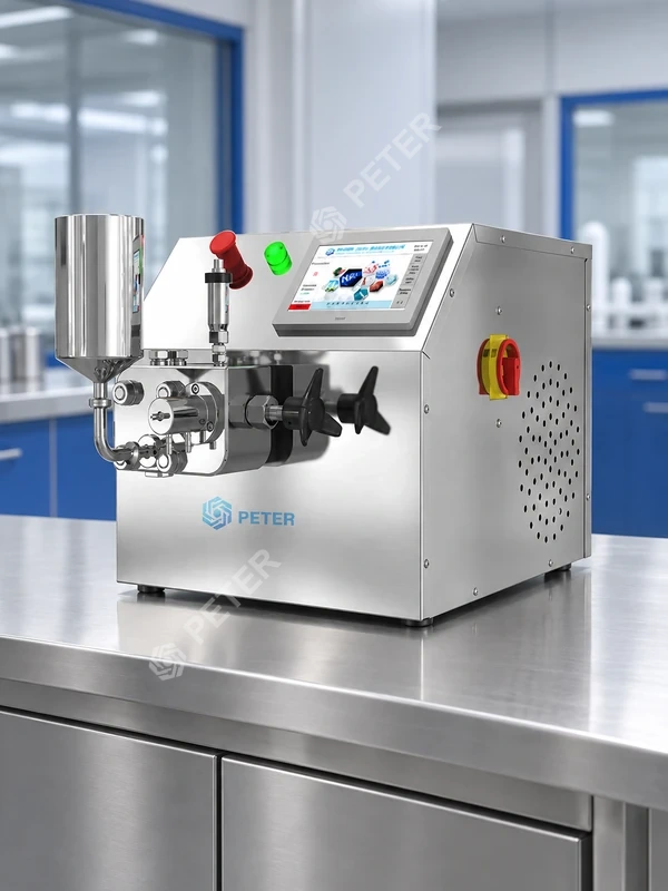
CAS PETER can enter the discussion after those boundaries are clear. A team evaluating an adjustable high pressure valve homogenizer should request configuration-specific documentation and a trial plan instead of inferring internal geometry or performance from the product class.
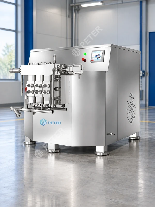
For emulsion-focused work, the same evidence rule applies when reviewing a high pressure homogenizing emulsifier: screen the proposed configuration against feed compatibility, working process window, sampling, cleaning, and maintenance requirements. No product certification or outcome should be inferred from a category name alone.
Questions about valve operation and process settings
What is the working principle of a high-pressure homogenizer?
A pump raises the pressure of a pumpable feed and sends it through a controlled valve or interaction zone, where the rapid pressure drop creates intense localized flow stresses. The balance of shear, extension, turbulence, impact, and cavitation depends on the geometry and fluid, so the working principle should be described as a sequence and verified for the proposed configuration.
How does a high-pressure homogenizer create a uniform product?
It can reduce droplets, disperse agglomerates, or disrupt cells when the interaction-zone stresses exceed the structure’s resistance. Uniformity also depends on the premix, stabilizer or formulation, temperature, pass history, sampling, and measurement method; the homogenizer cannot correct an unstable interface or unsuitable feed by pressure alone.
What is the role of high-pressure homogenization in the process?
It is usually a controlled size-reduction, dispersion, emulsification, or disruption step within a larger process that includes feed preparation, cooling, sampling, and downstream handling. Its role must be tied to a measurable product attribute and should not be confused with batch high-pressure processing, generic mixing, or a universal sterilization step.
Which process settings affect high-pressure homogenizer performance?
Key settings and conditions include valve or chamber class, pressure by stage, measured flow, inlet and outlet temperature, pass or recirculation definition, cooling, and sampling point. Feed viscosity, concentration, incoming size, pH, interfacial formulation, entrained air, hold time, and wear condition can also change the result.
Sources for particle-size measurement and process validation
- Grumbach, C., Krüger, V., and Czermak, P. “A New Control Strategy for High-Pressure Homogenization to Improve the Safety of Injectable Lipid Emulsions.” Pharmaceutics 14(8), 2022. Public full text. This formulation-specific study is cited as evidence that pressure, temperature, and cycles interact; it is not a universal process recipe.
- International Organization for Standardization. ISO 13320:2020, Particle size analysis—Laser diffraction methods. Official standard page.
- International Organization for Standardization. ISO 22412:2017, Particle size analysis—Dynamic light scattering (DLS). Official standard page.
- International Council for Harmonisation. ICH Q8(R2), Pharmaceutical Development, August 2009. Official guideline.
Control the full process to keep results repeatable
The decisive distinction is between nominal pressure and a reproducible pressure-drop event. First confirm that the feed is compatible and delivered without starvation or air; then define the valve or interaction approach, pressure by stage, actual flow, temperature window, and pass history; finally, sample consistently and test with a suitable, controlled method. Do not skip the cleaning boundary, wear baseline, or application-specific validation simply because a particle-size result looks acceptable. CAS PETER’s high-pressure homogenizer and microfluidizer range can support a model-level discussion once the process brief is complete, but selection should follow documented feed and quality requirements. Share the intended formulation and operating window, and request a trial and documentation plan before converting a promising run into a procurement specification.