

Valve Homogenizer: Functions Uses and Maintenance Guide
When a laboratory or pilot team sees pressure drift, rising outlet temperature or a changing particle-size result, the valve is often blamed first. The more useful diagnosis starts earlier: a valve homogenizer is a complete feed-to-interaction process, and its result depends on inlet stability, valve or chamber geometry, flow, pressure drop, cooling, passes, sampling and wear condition. A valve that performs well with a low-viscosity test liquid may behave differently with a concentrated suspension, emulsion or biological feed. This guide explains the valve homogenizer’s functions, common uses, selection boundaries, maintenance controls and validation methods so lab managers, materials researchers and procurement teams can compare equipment using process evidence rather than a maximum-pressure number.
Summary: A valve homogenizer uses a pump to drive a pumpable feed through a controlled restriction or interaction zone. The pressure drop creates localized velocity gradients and energy dissipation that can reduce droplets, disperse agglomerates, emulsify phases or disrupt cells. The useful specification includes feed envelope, working pressure, measured flow, valve or chamber class, temperature history, pass definition, cleaning route and acceptance method. ISO 13320 covers laser diffraction and ISO 22412 covers dynamic light scattering; neither certifies a homogenizer. Start with the product endpoint and representative feed, then verify pressure stability, heat, recovery, cleanability and wear before selecting a configuration.
What does a valve homogenizer do?
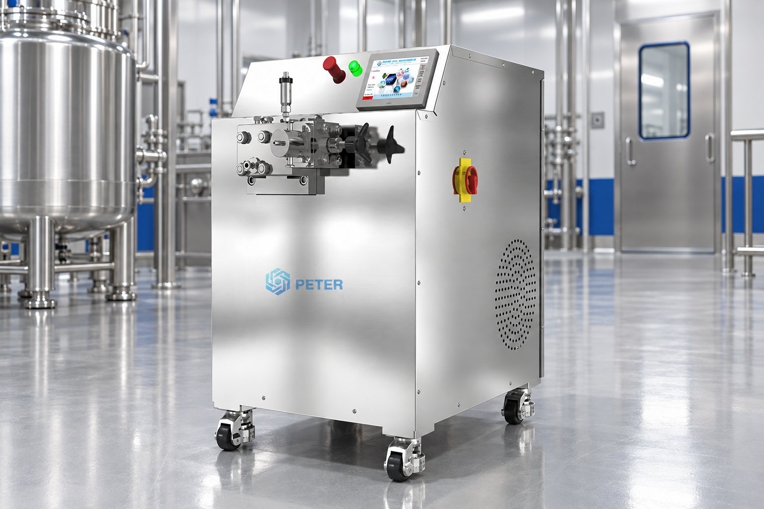
A valve homogenizer applies mechanical energy to a fluid by forcing it through a defined restriction. A positive-displacement pump or another pressure-generating arrangement supplies the pressure, while the valve or interaction zone controls how that pressure is released. As the stream accelerates and then expands or decelerates, the material can experience combinations of shear, elongational flow, turbulence, impact and decompression. The balance depends on the supplied geometry and the properties of the feed; no single mechanism should be assumed for every machine.
Its functions are practical rather than generic. The same equipment class may be used to reduce droplet size in an emulsion, deagglomerate a suspension, improve the uniformity of a dispersion, disrupt cells, or prepare a fluid for downstream filtration. The correct endpoint must be defined in measurable terms: a particle or droplet-size distribution, extraction yield, viscosity window, microscopy result, cell-lysis marker, stability after a hold, or another quality attribute. A visually uniform outlet is not sufficient evidence of performance.
A pressure gauge is only one observation. It indicates pressure at a measurement point and does not describe the local stresses, residence-time distribution, thermal peak or condition of every fluid element. A stable pressure reading can coexist with inlet starvation, gas entrainment, valve wear, inconsistent flow or a drifting analytical method. The useful process record links the gauge reading to actual flow, temperatures, feed condition, pass history and the named test method.
How does valve geometry change the process?
Valve geometry determines how pressure is allocated, how the stream enters and leaves the restriction, and how much surface area is exposed to wear or fouling. Supplier documentation may describe a single-stage valve, a two-stage arrangement, an adjustable valve, a fixed interaction chamber or another named configuration. Procurement should record the supplied class, intended feed envelope, working limits, pressure definition, cooling arrangement, hold-up and cleaning access. Internal dimensions or proprietary flow paths should be used only when documented by the supplier.
In a single-stage design, the primary pressure drop is concentrated in one controlled interaction. In a two-stage design, a first stage may provide the main treatment and a second stage may apply a separate pressure drop for a supplier-defined purpose. The pressure split, flow path and intended contribution must be confirmed for the actual model; “two-stage” does not mean two equal treatments or two complete passes. A fixed-path chamber can offer a repeatable geometry, but the claimed performance still depends on feed, pressure, flow, temperature and pass history.
| Valve or chamber approach | Potential use | What to document | Selection caution |
|---|---|---|---|
| Single-stage adjustable valve | Flexible dispersion, emulsification or cell-disruption screening | Working pressure, valve setting, flow, feed limits, temperature and wear baseline | Adjustment position alone does not quantify local stress or endpoint |
| Two-stage valve | Applications requiring a supplier-defined primary and secondary pressure drop | Pressure at each stage, purpose of stage two, flow, cooling and sample point | Two stages are not automatically two passes or equal energy inputs |
| Fixed interaction chamber | Repeatable treatment when the supplied chamber suits the feed | Chamber class, compatible feed, pressure, flow, hold-up, cleaning and spares | A chamber label does not prove equivalence to another geometry |
Where are valve homogenizers used?
Valve homogenizers are used wherever a pumpable material needs controlled size reduction, dispersion, emulsification or disruption. Food and beverage formulations may use them to reduce separation or improve mouthfeel; pharmaceutical and cosmetic development may use them to study emulsions, suspensions or active-ingredient distribution; materials researchers may use them for nanoparticle, pigment or ceramic dispersions; and biotechnology teams may use them for cell disruption when the feed and temperature window are suitable. These are application categories, not guarantees of a result.
For cell work, define the required biological endpoint and protect the downstream assay. The high-pressure cell-lysis guide explains why cell type, buffer, passes, cooling and measurement need to be considered together. For dispersion or emulsion work, record the phase ratio, solids loading, viscosity, stabilizer system and hold-time stability. A valve homogenizer can create a smaller droplet or particle distribution while still producing an unstable formulation if the interface or chemistry is unsuitable.
Before scale-up, distinguish a discrete pass from recirculation. In a discrete route, the defined batch traverses the interaction zone once and is collected separately. In recirculation, batch-volume equivalents can be calculated from cumulative flow divided by usable batch volume, but that average does not prove every fluid element received the same exposure. The benchtop-to-pilot guide provides a useful framework for documenting hold-up, sampling and scale-up boundaries.
What feed conditions should be checked before selection?
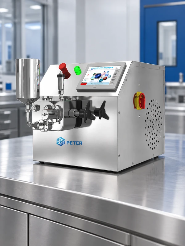
Document the feed before requesting a quotation. Record viscosity at the intended temperature, solids concentration, largest credible particle or agglomerate, pH, solvent, abrasiveness, volatility, foaming tendency, oxygen sensitivity and incoming particle or droplet distribution. Confirm that the pump, seals, valve, chamber, tubing and fittings are compatible with the chemistry and temperature. A stable feed vessel and sufficient inlet head are essential because gas or starvation can create pressure pulsation before the sample reaches the interaction zone.
Oversized particles, fibers or poorly wetted powder can block a narrow path or create rapid wear. A concentrated or viscous feed may require temperature control, premixing or a different flow arrangement. For biological materials, the buffer and cell concentration affect both pumpability and the acceptable thermal history. The supplier’s allowable feed range should be compared with the actual formulation, including cleaning and flush fluids.
Heat and recovery are part of compatibility. Pressure work and flow resistance generate heat; a cooler can lower the bulk temperature after the interaction zone while leaving a transient peak unrecorded. Record inlet, immediate outlet, cooled outlet, coolant condition and inter-pass hold time. Weigh loaded and recovered material, and include line hold-up, vessel or filter retention, start-up waste, flush volume and transfer losses. These data often change the total-cost decision more than a small difference in nominal pressure.
How should a valve homogenizer be selected?
Selection should begin with a process brief. State the target attribute, feed envelope, usable batch volume, required accepted throughput, temperature ceiling, pass or recirculation route, sampling plan, cleaning regime, containment needs, utilities, materials of construction, wear-part expectations and scale-up destination. Ask the supplier to distinguish maximum from continuous working limits and to identify the test fluid and conditions behind pressure and flow figures.
For a laboratory or early pilot evaluation, CAS PETER’s PT-20 high-pressure homogenizer page can help frame questions about configuration and trial support. For a larger development step, the PT-40 pilot-scale page provides a separate reference point. Ratings, wetted materials, cooling and options should be confirmed for the quoted configuration; product pages do not replace representative acceptance testing.
| Selection checkpoint | Evidence to collect | Why it matters |
|---|---|---|
| Target quality attribute | Method, acceptance limit, sample preparation, replicates and hold time | Links valve settings to a release or research decision |
| Feed and inlet | Viscosity, solids, particles, gas control, temperature, inlet head and chemistry | Separates feed instability from valve performance |
| Working duty | Pressure, measured flow, passes, route, cooling and accepted throughput | Prevents maximum ratings from being mistaken for usable capacity |
| Materials and cleaning | Wetted materials, seals, cleaning chemistry, access, residues and verification | Controls contamination, corrosion and downtime risk |
| Service and wear | Inspection criteria, wear parts, spares, lead times, training and safe disassembly | Makes lifecycle cost and recovery after service measurable |
What maintenance does a valve homogenizer need?
Maintenance has three layers: cleaning, condition inspection and performance verification. Clean the product-contact path using the supplier’s procedure and the chemistry appropriate to the formulation. Confirm that cleaning reaches the valve or chamber, gaskets, seats, tubing, sample ports, cooler and drain points. A clear rinse is not automatically proof of residue removal; define the residue of concern, sampling location, method recovery and acceptance limit for the application.
Inspect seals, valve seats, interaction components, pump check valves, gauges, filters, fittings and cooling circuits at the frequency set by duty, chemistry and supplier guidance. Look for leakage, scoring, erosion, deposits, abnormal pressure response, noise, vibration and temperature drift. Abrasive solids, high solids loading and aggressive cleaning can accelerate wear. Keep a baseline record after installation or qualified service so that later changes can be distinguished from feed or measurement variation.
After maintenance, verify assembly, pressure stability, flow, leakage, cleaning status and the agreed quality endpoint. A replacement part may restore pressure while changing the process result if its geometry or seating differs. Document the installed part, torque or assembly record where applicable, calibration status, test fluid, duty point and acceptance result. Do not bypass interlocks or improvise pressure-boundary repairs.
How can valve homogenizer problems be troubleshot?
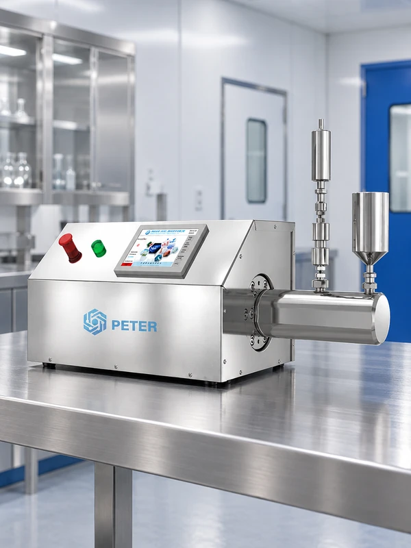
If pressure or flow fluctuates, check feed level, inlet head, suction restrictions, air entrainment, viscosity, temperature, pump filling, seals and sensor condition before changing the valve setting. If abnormal inlet noise or vibration appears, stop within the operating procedure and investigate possible starvation, blocked screens, volatile flashing, foam or loose components. A higher gauge reading is not a safe correction for an unstable inlet.
If the quality endpoint drifts at the same recipe, compare feed lot, premix, actual flow, temperatures, pass history, sampling point, sample age and analytical preparation before assigning the cause to valve wear. If outlet temperature rises, inspect cooling duty, flow, restriction, sensor location and fouling. If recovery falls, inspect hold-up, retained solids, transfers, foaming and flush requirements.
Use a retained baseline and a controlled test fluid to separate machine behavior from formulation behavior. Escalate when a pressure boundary leaks, a vessel or interaction component is damaged, a safety interlock fails, contamination cannot be ruled out or the accepted endpoint cannot be restored after basic checks. These boundaries protect both personnel and the validity of the process record.
How should valve homogenizer results be validated?
Use a fixed sampling plan that identifies startup material, steady-state collection, sample temperature, pass history, container, hold time and preparation. For particle-size work, ISO 13320:2020 covers laser diffraction and ISO 22412:2017 covers dynamic light scattering. They are method standards, not product certifications; a D90 from one method and a DLS statistic from another are not interchangeable without a justified correlation. Retain the unprocessed baseline and record dilution, dispersant, instrument settings and replicate rule.
For pharmaceutical development, ICH Q8(R2) supports linking material attributes and process parameters to critical quality attributes. For regulated manufacturing, 21 CFR 211.110 addresses written in-process controls and tests designed to monitor output and variability. Applicability depends on product, market and quality system. Neither source defines a universal valve setting, and neither makes a homogenizer “FDA certified.”
Acceptance testing should use the intended feed or a justified surrogate, the proposed duty point, a defined run duration, the required thermal window, the agreed cleaning state and a pass/fail rule. Include repeat runs where needed to estimate variation. A successful test must show that the complete process—feed, valve, cooling, sampling, measurement and cleaning—can be repeated, not merely that the machine reached a pressure setpoint.
Frequently asked questions about valve homogenizers
What is the difference between a valve homogenizer and a high-speed mixer?
A valve homogenizer pumps a fluid through a defined pressure-drop interaction zone, while a high-speed mixer usually applies local mechanical energy through a rotor-stator or similar head in a vessel. The two routes can support different feed states, residence histories and scale-up assumptions. Compare them using the same feed, endpoint, temperature limit and analytical method.
Can a valve homogenizer process viscous or abrasive samples?
It may be possible when the pump, valve, seals and wetted materials are rated for the actual viscosity, solids and chemistry. Viscous or abrasive feeds can change filling, pressure stability, wear and cooling demand, so a representative trial and supplier review are needed. Do not infer compatibility from a water-based flow claim.
How many passes should a valve homogenizer use?
There is no universal pass count. Define a physical pass or a recirculation measure, then determine the point at which the quality endpoint meets its acceptance limit without unacceptable heat, recovery loss, energy or wear. Record route, batch volume, measured flow, sampling time and temperature so “passes” remains auditable.
What maintenance does a valve homogenizer need?
It needs documented cleaning, inspection of seals and interaction components, checks of pumps, gauges, filters, fittings and cooling circuits, and post-service performance verification. Frequency depends on duty, formulation, abrasiveness, pressure and the supplier’s instructions. Keep critical spares and a baseline test so pressure drift or quality drift can be investigated promptly.
References
- ISO 13320:2020, Particle size analysis — Laser diffraction methods.
- ISO 22412:2017, Particle size analysis — Dynamic light scattering.
- International Council for Harmonisation, ICH Q8(R2), Pharmaceutical Development.
- U.S. eCFR, 21 CFR 211.110, Sampling and testing of in-process materials and drug products.
- U.S. FDA, Process Validation: General Principles and Practices (2011).
Conclusion
A valve homogenizer should be purchased and maintained as a complete, measured process rather than as a pressure rating. Define the feed and quality endpoint first; then match valve or chamber geometry, pressure, flow, cooling, passes, materials and cleaning to that boundary. Validate the result with consistent sampling and a suitable test method, and use wear, recovery, heat and service evidence to estimate total ownership cost. ISO and regulatory references support measurement and process control, but they do not certify a universal setting or outcome. CAS PETER’s high-pressure homogenizer range can support a configuration and trial discussion once the process brief is clear. The durable choice is the valve system that reproduces the required endpoint, remains cleanable and serviceable, and leaves a traceable record after every intervention.