

High-Pressure Homogenizer Pressure Calibration: A Practical Guide
High-pressure homogenizer pressure calibration should establish how the installed pressure indication relates to a suitable reference across the operating range used by the process. A useful record identifies the instrument, units, pressure reference, test conditions, deviations and measurement uncertainty. Check the sensor-to-display chain as well as any separate gauge, and assess the result against a predefined process requirement. Calibration is distinct from adjusting an instrument, checking pressure stability during production or testing a protective shutdown. Work on the pressure boundary belongs to competent personnel using an approved procedure and compatible, rated equipment.
This guide helps engineers and buyers specify the evidence they need, review a calibration certificate and decide what an unexpected result means for earlier batches. For an overview of the machine and processing zone, start with our high-pressure homogenizer working-principle guide.
Define which pressure the process actually uses
Before reviewing an accuracy claim, identify the measurement point. A pressure value upstream of a homogenizing restriction is not automatically the pressure drop across every stage. Backpressure and the arrangement of multiple stages matter. The drawings and operating instructions should show what each gauge or transmitter measures and how the displayed value is used by the recipe.
Record whether pressure is expressed relative to atmosphere, relative to a vacuum reference or as a differential measurement. Also record the unit and full measurement range. A certificate for an absolute-pressure transmitter cannot be read as though its zero reference were gauge pressure. Avoid relying on a unit abbreviation without the instrument specification.
For a two-stage machine, establish which indication represents the total upstream pressure and which represents a separate stage or downstream condition. Our single-stage and two-stage comparison provides process context. The calibration request should follow the actual installed design rather than assuming every machine has identical sensing points.
Separate calibration, adjustment and functional checks
Calibration determines a relationship between indication and reference under stated conditions. Adjustment changes the instrument response. A zero check is narrower: an apparently correct zero does not establish accuracy over the working range. Keep these activities separate in the equipment record so the team can understand what was measured and what was changed.
Pressure stability during a run is another question. A correctly calibrated instrument may reveal real process pulsation, while a heavily averaged display can look steady despite a changing input. Investigate acquisition rate, filtering and the physical process before treating every unstable trace as a calibration problem.
A protective pressure trip also has a different purpose. Its functional test needs an approved method, defined conditions and an acceptance criterion. A measurement certificate alone does not prove that a shutdown acts correctly. See the homogenizer safety-device guide for the broader protection discussion.

Map the complete sensor-to-record chain
A digital system may include a sensing element, transmitter electronics, an input channel, scaling, the operator display and a data record. Decide which parts the proposed calibration covers. A sensor calibrated separately from the machine does not by itself establish that an incorrectly scaled display or exported record is correct.
Ask for a simple channel map linking each instrument identifier to its location, display tag and recorded variable. Compare engineering units and range settings across the chain. If a replacement instrument has a different output or range, the installation and scaling need controlled review before the equipment returns to service.
| Evidence item | What to confirm | Why it matters |
|---|---|---|
| Instrument identity | Serial number, channel tag, range and measurement point | Connects the result to the actual machine |
| Calibration scope | Sensor alone, transmitter, display or complete indication chain | Prevents an untested component from being assumed correct |
| Reference and uncertainty | Reference identity, traceability statement and uncertainty for the result | Supports a meaningful accuracy assessment |
| Measurement results | Applied values, indications, deviations and relevant direction effects | Shows behavior across the range rather than one convenient point |
| Adjustment history | As-found result and, when changed, as-left result | Supports review of earlier production and the returned instrument |
| Use decision | Agreed tolerance, decision rule and unresolved exceptions | Connects calibration evidence to the intended process |
This table is a document-review checklist, not a universal calibration procedure. The laboratory must select an appropriate method for the instrument and application.
Ask for traceability and uncertainty together
NIST’s metrological-traceability guidance explains that a measurement result is related to a stated reference through a documented chain of calibrations, each contributing uncertainty. A label saying “traceable” is therefore less useful than a report that identifies the result, its uncertainty and the supporting reference.
Traceability does not establish fitness for every process. The remaining uncertainty may be too large for a narrow operating requirement, even when the reference chain is valid. Review the uncertainty at the relevant pressure points and confirm that the proposed service can support the actual decision you need to make.
Do not assume that a national-metrology reference means the entire homogenizer was calibrated by that institute. Ask who performed the work, what was calibrated and what the reported statement covers. These questions also help distinguish a genuine instrument record from a generic supplier brochure or an unrelated certificate.
Review range coverage and direction effects
The calibration should cover a justified range related to intended use, including the operating region that matters to the process. A result at a low pressure does not establish performance at an untested high-pressure point. Agree the test range and reporting needs before sending an instrument away or scheduling service.
EURAMET Calibration Guide No. 17 addresses calibration of mechanical and electromechanical manometers, including measurement deviations and uncertainty. It provides a basis for reviewing relevant effects such as repeatability and hysteresis within its stated scope. It is guidance for calibration practice, not a homogenizer operating manual or a blanket requirement for every sensor technology.
Where increasing and decreasing pressure results differ, retain that information rather than reporting only an average that conceals the difference. Similarly, a return-to-zero shift or inconsistent repeated readings deserves explanation. The laboratory should report the conditions and interpretation appropriate to its method.
Interpret a numerical result without inventing an acceptance rule
Consider an illustrative point where the applied reference pressure is 100.0 MPa and the installed indication reads 101.0 MPa. The indication error is 101.0 minus 100.0, or +1.0 MPa. A correction to that indication would have the opposite sign. Keep error and correction distinct when transferring information into a controlled record.
Suppose the reported expanded uncertainty of that error is 0.4 MPa and the agreed permitted error is ±1.2 MPa. The nominal error lies inside the tolerance, but its uncertainty interval extends beyond the positive limit. Whether this supports a pass depends on the agreed decision rule. Do not silently choose the most favorable interpretation after seeing the result.
These values demonstrate arithmetic only. They are not CAS PETER specifications, a recommended tolerance or calibration data. Define the required accuracy from the process and measurement system, then agree how uncertainty will affect acceptance before reviewing the certificate.
Preserve as-found results before adjustments
When an instrument is checked after a period of use, its as-found condition helps assess whether earlier records may have been affected. If adjustment is needed, preserve that result and the separate as-left result. A final “within tolerance” statement after adjustment cannot explain how the instrument behaved before the work.
If the as-found result is unacceptable, determine the potentially affected interval using the available evidence: earlier satisfactory checks, maintenance events, unusual trends and the nature of the deviation. A responsible quality and engineering review should decide whether earlier process decisions require reassessment. Avoid assuming that all previous material failed, or that a successful adjustment removes the need for review.
Record the instrument’s return to service, the accepted configuration and any follow-up checks. Where equipment qualification applies, link the work to the relevant controlled documents. The homogenizer qualification-document guide explains the wider documentation structure.
Choose intervals from evidence and risk
There is no universal calibration interval for every homogenizer pressure instrument. Consider manufacturer recommendations, operating exposure, pressure cycling, previous drift, consequences of an incorrect result and the site’s quality requirements. Review the interval after replacement, overload, damage or a significant change in use.
A planned interval should have an owner and a due-date process. Interim checks can provide useful evidence but should have a defined purpose and acceptance basis. Comparing two unidentified gauges that share the same unknown bias does not create a trustworthy reference.
Keep process troubleshooting separate from this schedule. If feeding or cavitation changes, the pressure behavior may change for a real mechanical reason. Restore a controlled process condition using the approved troubleshooting procedure rather than adjusting the instrument to hide a genuine disturbance.
Plan service without compromising the pressure boundary
The HSE guidance on using pressure systems emphasizes safe operating limits, maintenance and competent examination where applicable. Instrument removal and testing must follow the equipment manufacturer’s isolation and depressurization procedure. A display showing zero alone is not a complete safe-work authorization.
Confirm pressure rating, wetted-material compatibility, cleanliness and connection details with the responsible supplier or service provider. Do not improvise adapters, add a reference gauge to an unapproved port or run the machine beyond its permitted range to reach a convenient test point. This article does not replace the installation’s safe-work procedure.
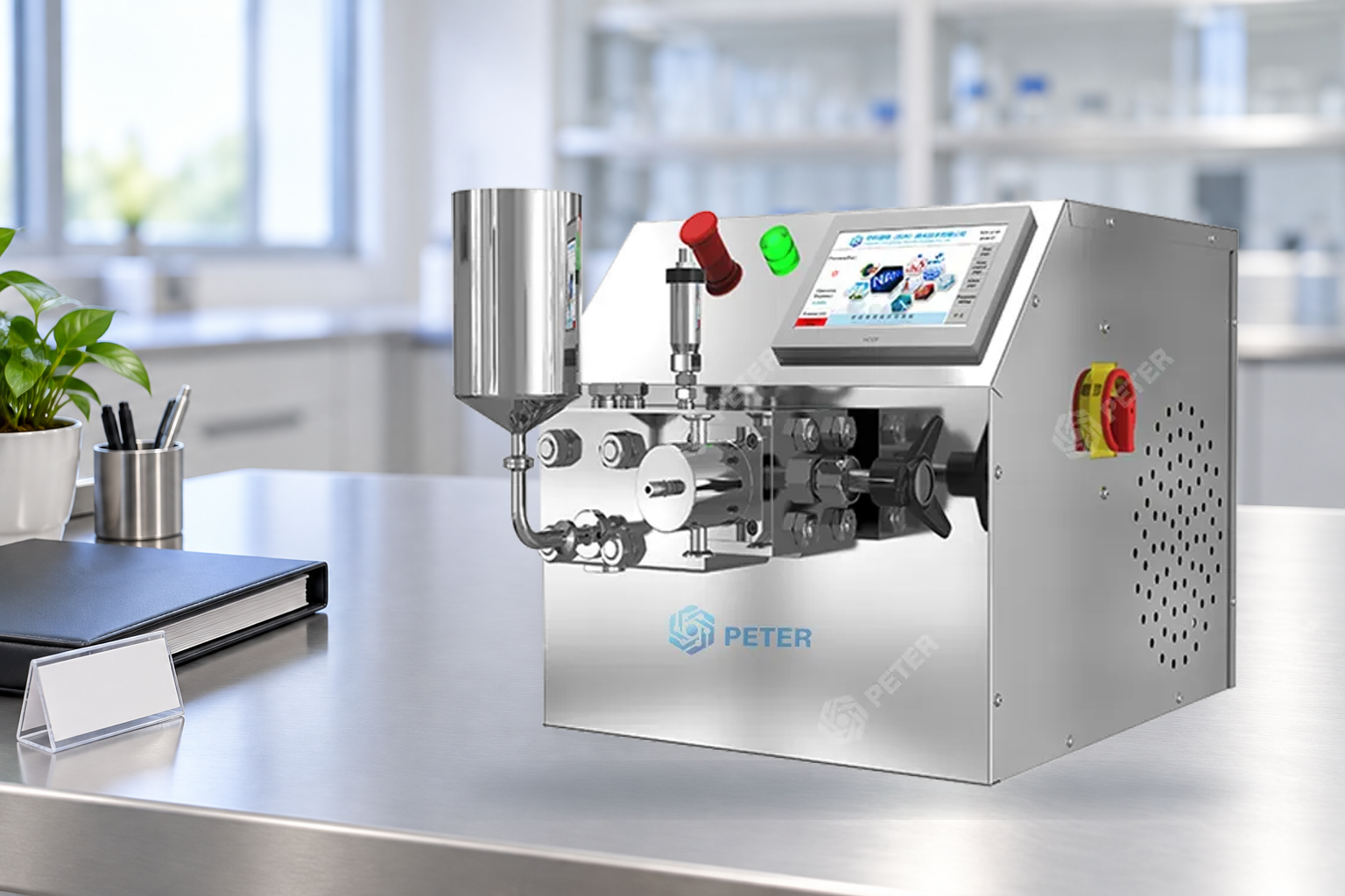
When discussing a CAS PETER PT-20 homogenizer, request the installed pressure-measurement specification and the available calibration evidence for that configuration. The product photograph identifies equipment; it does not demonstrate a completed calibration or a stated accuracy.
Learn the measurement principles
The NPTEL lecture below, taught in a chemical-engineering instrumentation course, explains pressure measurement. Use it as background to understand measurement concepts, not as instructions for connecting test equipment to a homogenizer.
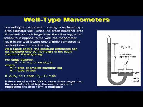
Watch the NPTEL pressure-measurement lecture.
Frequently asked questions
Does a calibration sticker prove pressure accuracy?
No. Review the instrument identity, range, results, uncertainty and decision rule in the supporting record. A sticker alone does not describe the accuracy at the pressure your process uses.
Is pressure calibration the same as a safety-trip test?
No. Calibration assesses measurement indication against a reference. A safety-trip test checks a protective function under an approved procedure and needs its own acceptance evidence.
Should a pressure transmitter be checked with the display?
Define the scope around the decision being made. A separately calibrated transmitter does not prove that the installed display scaling or recorded values are correct.
What if the as-found pressure result is outside tolerance?
Preserve the result, document any adjustment and assess the possible effect on earlier process records. The responsible engineering and quality team should decide the affected interval and follow-up actions.